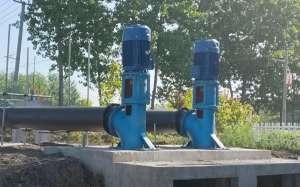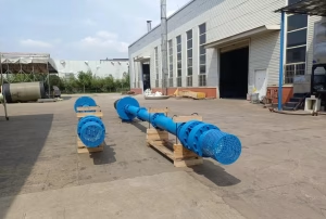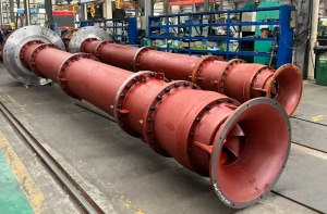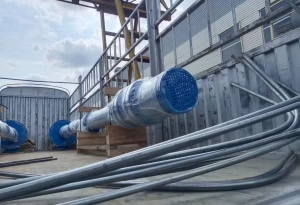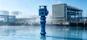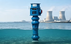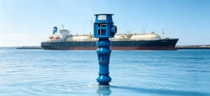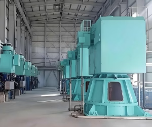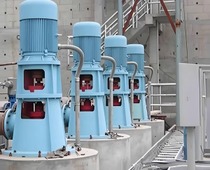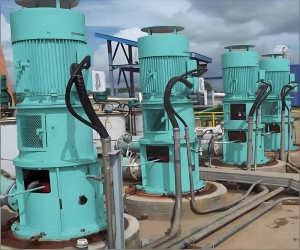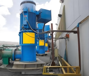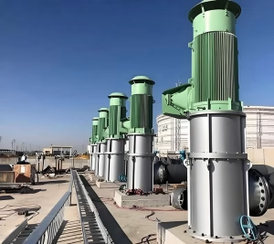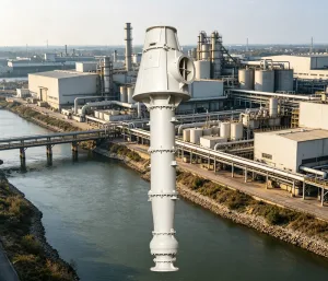
A vertical turbine pump (VTP) is a type of centrifugal pump designed to lift water vertically from deep wells, sumps, reservoirs, or open-water sources. Understanding the vertical turbine pump working principle and diagram is essential for engineers, plant operators, and students who work with municipal water supply, irrigation, fire protection, and industrial pumping systems.
In this guide, we break down exactly how a vertical turbine pump works, walk through a labeled diagram of its main components, and explain why it’s one of the most reliable pump designs for high-capacity, deep-set applications.
What Is a Vertical Turbine Pump?
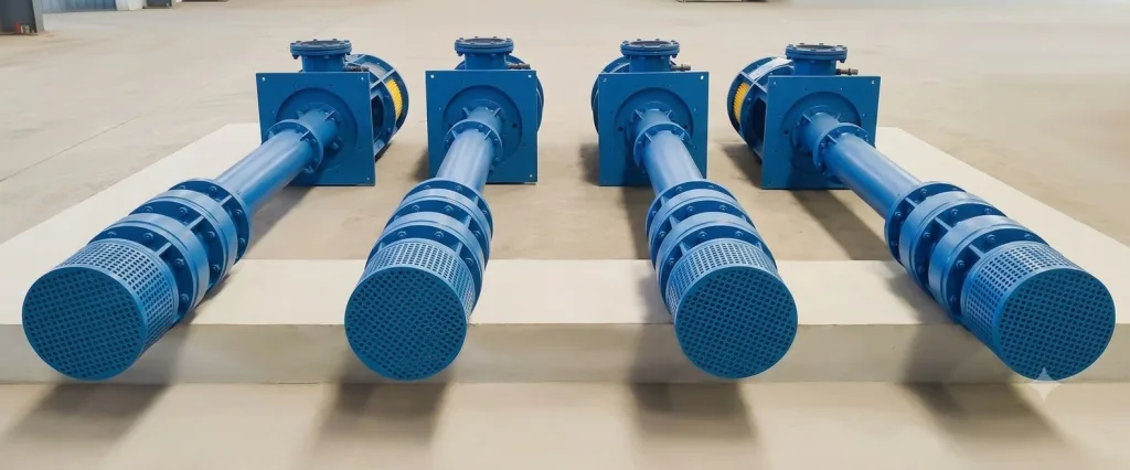
A vertical turbine pump is a multi-stage centrifugal pump installed with its shaft oriented vertically. Unlike horizontal centrifugal pumps, a VTP is built to be partially or fully submerged in the water source, with the motor mounted above ground and connected to the submerged pump bowls by a long vertical shaft and column pipe.
Because the stages can be stacked one on top of another, vertical turbine pumps can generate very high heads (pressure) while keeping a compact footprint — making them ideal for deep wells and large-capacity applications where a horizontal pump simply wouldn’t fit or wouldn’t have enough suction lift.
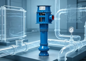
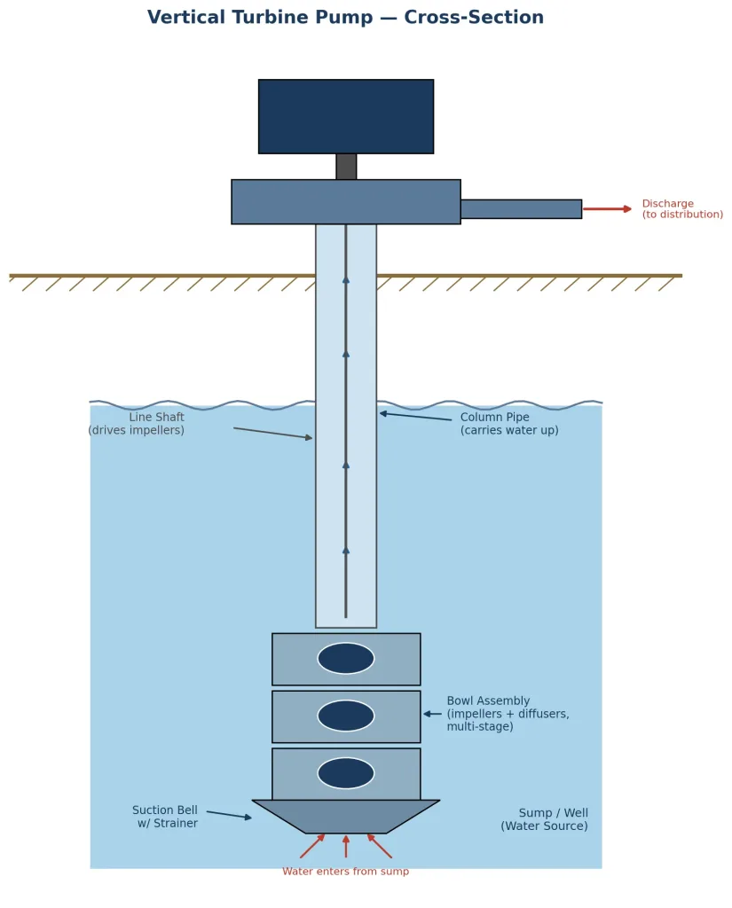
Vertical Turbine Pump Diagram (Cross-Section)
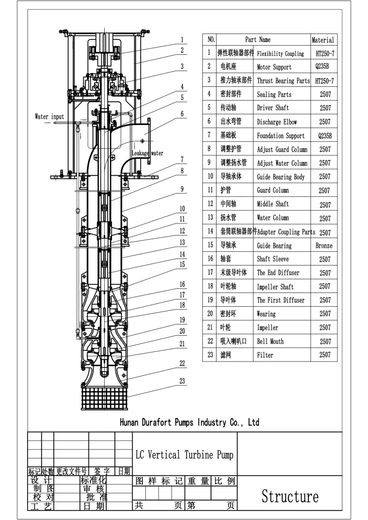
The diagram below shows the main components of a vertical turbine pump, from the motor at the top down to the submerged suction bell at the bottom.
Key Components Explained
| Component | Function |
|---|---|
| Motor | Mounted above ground; supplies rotational power to the line shaft |
| Discharge Head | Redirects pumped water from the vertical column into the horizontal discharge pipeline; also supports the motor |
| Column Pipe | Vertical pipe that carries water from the bowl assembly up to the discharge head |
| Line Shaft | Connects the motor to the impellers; runs through the center of the column pipe |
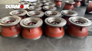
| Bowl Assembly | Houses the impellers and diffuser vanes; where the actual pumping (energy transfer) happens |
| Impeller(s) | Rotating component that adds velocity (kinetic energy) to the water |
| Diffuser (Bowl) Vanes | Stationary vanes that convert the water’s velocity into pressure (head) |
| Suction Bell / Strainer | Submerged inlet that draws water in while filtering out debris |
Vertical Turbine Pump Working Principle
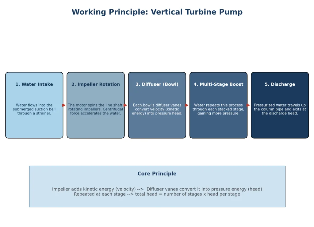
The vertical turbine pump working principle relies on converting mechanical (rotational) energy into hydraulic energy through a series of impeller-diffuser stages. Here’s the step-by-step process:
Step 1: Water Intake
Water enters through the submerged suction bell, passing through a strainer that keeps out sand, debris, and large particles before it reaches the impeller.
Step 2: Impeller Rotation
The motor drives the vertical line shaft, which spins the impeller(s) inside the bowl assembly at high speed. As the impeller rotates, centrifugal force accelerates the water outward, increasing its velocity.
Step 3: Diffuser Action (Pressure Conversion)
Surrounding each impeller is a set of stationary diffuser vanes. These vanes slow the water down in a controlled way, converting its kinetic energy (velocity) into pressure energy (head) — this is the core energy-conversion step of centrifugal pumping.
Step 4: Multi-Stage Boost
In a single-stage pump, this process happens once. In a multi-stage vertical turbine pump, water flows from one bowl into the next, repeating the impeller-diffuser cycle at each stage. Each additional stage adds more head, so total pump head is roughly proportional to the number of stages.
Step 5: Discharge
Once the water has passed through all stages, it travels up the column pipe to the discharge head at the surface, where it’s redirected into the horizontal discharge piping for distribution.
In short: impeller adds velocity → diffuser converts velocity into pressure → repeat per stage → water is discharged at the required head and flow rate.
Types of Vertical Turbine Pumps
- Wet-Pit (Open Line Shaft) VTP – line shaft runs through open water in the column; simple and economical, common in irrigation and water supply.
- Wet-Pit (Enclosed/Oil-Lubricated Line Shaft) VTP – shaft runs inside an enclosing tube lubricated by oil, protecting it from abrasive or contaminated water.
- Submersible Turbine Pump – the motor itself is submerged with the pump bowls, eliminating the long line shaft entirely (a close relative of the VTP, common in deep boreholes).
- Can (Barrel) Type VTP – mounted inside a can/barrel and used above ground, often for boiler feed or condensate applications where the source is not naturally deep.
Common Applications
- Municipal water supply and water treatment plants
- Deep well irrigation
- Fire protection / fire pump systems (NFPA 20 fire pumps)
- Flood control and stormwater pumping stations
- Power plant circulating water and condensate systems
- Industrial process water and cooling tower makeup
Advantages of Vertical Turbine Pumps
- High efficiency at high heads and large flow rates
- Compact footprint — ideal where horizontal space is limited
- No need for pump priming since the bowl assembly is submerged
- Multiple stages can be added to reach the required head
- Motor stays accessible above ground for easy maintenance
Common Limitations
- More complex installation and alignment (long shaft must stay straight and true)
- Line shaft bearings require lubrication (water or oil) and periodic inspection
- Pulling the pump for major repairs can be labor-intensive due to pump setting depth
- Sensitive to sand/abrasive content in the water source unless properly designed
Vertical Turbine Pump vs. Horizontal Centrifugal Pump
| Feature | Vertical Turbine Pump | Horizontal Centrifugal Pump |
|---|---|---|
| Orientation | Vertical shaft, submerged stages | Horizontal shaft, above-ground casing |
| Priming | Self-priming (submerged) | Usually requires priming |
| Footprint | Small (compact, vertical) | Larger horizontal footprint |
| Best for | Deep wells, sumps, high head | Surface water, shorter suction lift |
| Maintenance access | Requires pulling the column/bowl assembly | Easier, more accessible |
Frequently Asked Questions
1. What is the main working principle of a vertical turbine pump? It works on the centrifugal principle: an impeller adds velocity to the water, and diffuser vanes convert that velocity into pressure, with the process repeated across multiple stages to build up head.
2. Why is the pump called “vertical turbine”? Because the shaft, impellers, and bowl assembly are arranged vertically, and the multi-stage bowl assembly historically resembled a turbine arrangement.
3. Can a vertical turbine pump run dry? No. Since it depends on the bowl assembly being submerged, running dry can cause the line shaft bearings to overheat and fail — a minimum submergence level must always be maintained.
4. How many stages can a vertical turbine pump have? It varies by application, but VTPs commonly range from a single stage up to 10+ stages depending on the required head.
Conclusion
Understanding the vertical turbine pump working principle and diagram makes it much easier to select, install, and maintain the right pump for deep-well and high-head applications. At its core, the pump relies on a simple but powerful idea: spin the impeller to add velocity, then use the diffuser to convert that velocity into pressure — repeated stage after stage until the water reaches the surface with the head and flow you need.
Whether you’re specifying a pump for a municipal water system, irrigation project, or fire protection system, knowing how each component — from the suction bell to the discharge head — works together will help you troubleshoot issues faster and keep your system running efficiently.